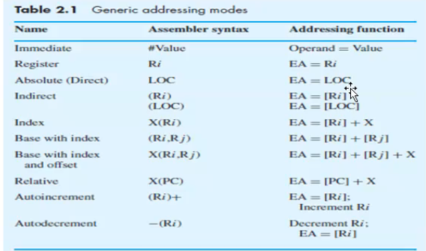
Registrer Addressing
Direct/Absolute Addressing
the operand is in a memory location; the address of this location is given explicitly in the instruction.
eg: Move LOC, R2
Immediate Addressing
the operand is given explicitly in the instruction eg: Move #300,R0
Add #6,R1 Effective address = value
Indirect Addressing
The Efficitive address of the oprand is the contents of a register or memory loc whose address appears in the instruction
We denote a indirection by placing the name of register or memory address given in the instruction in parentheses.
The register or memory location contains the address of operand is called a pointer
eg: Add (R1),R0
Indexed/Displacement Addressing
Index mode - the effective address of the operand is generated by adding a constant value to the contents of a register
index register holds address of a new location and calure of X defines an offset(displacement)
eg: Add 20(R1),R2
R1+20 is the correct address of the value we need
Indexing and Arrays
X(Ri) -> Ea = [Ri] + X
(Ri,Rj) -> Ea = [Ri] + [Rj]
X(Ri,Rj) -> Ea = [Ri] + [Rj] + X
RElative addressing (PC-Relative)
EA is determined by index mode using the program counter in place of the general purpose register.
eg: X(PC) ; EA = [PC] + X (X is a signed number)
AutoIncrement mode
The effective address of the oprand is the contents of a register specified in the instruction
After accessing the opteand , the contents of this register are increment automatically eg: (Ri) -> Ea = Ri
Increment Ri
AutoDecrement mode
Contents of a register specified in the instruction is automatically decremented and used as effective address of the operand
(Ri) -> Decrement Ri
Ea = Ri
Basic Processing Unit
Executing an Instruction
Fetch Phase
Fetch the contents of the memory location pointed to by the PC.The contents of this location are loaded into the IR.
Exeecution Phase
Executes the instruction in the IR
Single Bus Organization
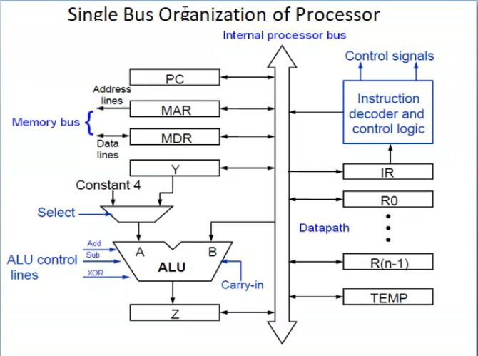
MDR has 2 input and 2 output
MAR- input[ processpr bus to MAR ] and 2 output
Control signals - controll all the operation , connected to the memory bus
General Purpose Registers [R0, … R(n-1)]
Y,Z,Temp -store value
img 2
Ri out is set ot 1 -> out is possble Rj in is set to 1 -> input is possible